


TSP Series · Positive displacement
Triple Screw Pumps
TSP positive displacement pump technology, designed and engineered for high efficiency and exceptionally long service life. Three intermeshing rotors move fluid from suction to discharge in sealed, continuously advancing chambers, with no pre-compression and virtually no pulsation.
API 676 compliant models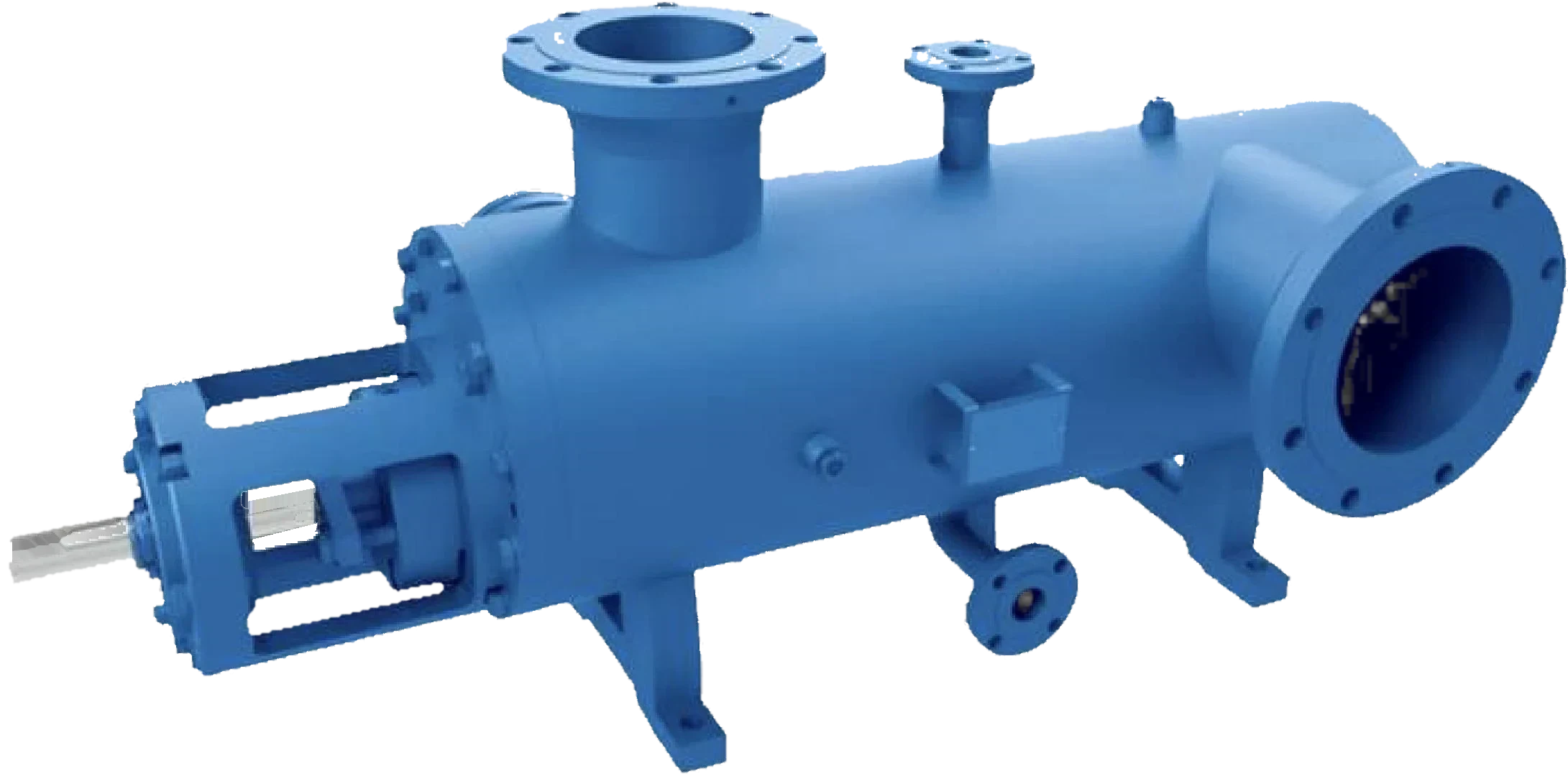
Introducing triple screw pumps
Worldwide, pumps of all types are critical to industry. SPS Triple Screw Pumps are no exception.
A TSP pump is a rotary positive displacement machine: a casing encloses one driven power rotor and two sealing idler rotors. Because displacement is fixed by geometry, flow is proportional to speed and almost independent of pressure, which is why the same pump family covers a wide range of applications in nearly every market worldwide.
Typical Applications
- Crude Oil – LACT Stations, Booster, High Pressure
- Fuel Oil Systems
- Lubricating Oil Systems
- Hydraulic Oil Systems
- Machine Tool Service
- Viscous Process Liquids
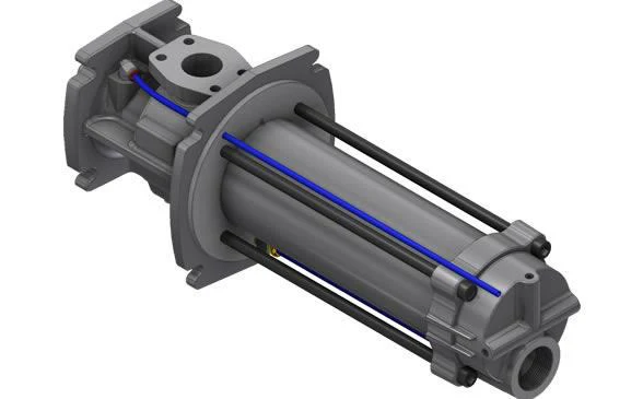
Unique features and benefits
What the design gives you
Each advantage traces back to one mechanical idea: three symmetrical rotors that seal against each other and the housing, and carry fluid axially instead of squeezing it.
Long service life
Axial loads on the power rotor and idlers are hydrostatically balanced and the idlers ride on a hydrodynamic fluid film, so the rotating parts are not fighting their own pressure loads. The result is little maintenance compared to plunger pumps and gear pumps, as well as single-stage and multistage centrifugal pumps.
Pulsation-free flow
The three internal rotor geometry hands fluid from one chamber to the next in an overlapping sequence, giving virtually pulsation-free flow. As a result, pulsation dampeners are not required, unlike other pumping technologies.
Precise flow control
Continuous meshing of the screws ensures a constant and predictable flow rate at a given speed, producing a smooth, near pulsation-free flow that is easy to meter, blend and control with a VFD.
High overall efficiency
Low internal recirculation, low friction losses from the hydrodynamic principle and smooth continuous flow combine to give lower power consumption than competing designs.
Compact design
High pressure is generated along a single rotor set inside one casing, so the pump requires a much smaller footprint than plunger and multistage centrifugal pumps of equivalent duty.
Low noise level
Very low airborne and structure-borne noise emissions: up to 15–20 dB lower than conventional gear pumps, and often lower than the electric motor driving the pump. Normal noise levels for triple screw pumps are typically below 75 dB(A).
Various viscosities
The intermeshing screw design lets one pump family handle a wide range of fluid viscosities efficiently, from thin condensate to heavy crude.
Low viscosity · 1.2 to 400 cP
The pump can operate at higher speeds, increasing flow rates from the same frame size.
High viscosity · 400 to 5000 cP
The pump operates at lower speeds while maintaining efficiency, preventing cavitation and ensuring proper fluid handling.
Contact SPS for applications below 1.2 cP.
Principles of operation
Simple intermeshing design
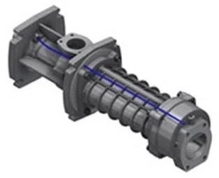
The cutaway below removes the near half of the casing and rotor housing. Watch the shaft, power rotor and idlers turn while fluid enters the end suction, is carried along the rotors in sealed closures and leaves through the top discharge.
This browser cannot display the 3D animation. Watch the MP4 version.
Cutaway rendered in the browser. Proportions, lead and clearances are representative, not a specific frame size. Rotor speed is slowed for clarity. Open the animation as an MP4 video
-
Fluid closure
The intermeshing threads of the power rotor and idler rotors, together with the close-tolerance housing, create a moving labyrinth seal. The enclosed volume is the fluid closure. It is this concept that gives the three-screw pump its positive displacement capability.
-
Continuous fluid movement
The rotating screws create a series of sealed chambers between the screw threads and the casing. These chambers move continuously from the suction side to the discharge side, producing a smooth, uninterrupted flow.
-
No pre-compression
The pumping element does not pre-compress the fluid. It transports it from suction to discharge; pressure is developed only against the system resistance at the outlet.
-
Overlapping fluid transfer
As one chamber is closing and expelling fluid, another is opening and accepting fluid. This overlap, together with an optimized screw profile, produces a uniform and continuous output with greatly reduced pressure pulsations.
-
Precise clearances
Tight tolerances and precise machining between the intermeshing screws and the pump casing minimize internal recirculation, ensuring a consistent flow rate as pressure rises.
-
Hydraulic balance
The symmetrical arrangement of the screws creates a hydraulically balanced system. Idler rotors generate a hydrodynamic film that provides radial support; axial loads created by differential pressure are hydrostatically balanced; and symmetrical pressure loading on the power rotor eliminates the need for bearings to absorb radial forces. Vibration and pulsation are reduced and pump life is dramatically increased.
From these efficiency-enhancing features, triple screw pumps achieve high performance where consistent, reliable fluid handling is critical.
Specifications and construction
Main components
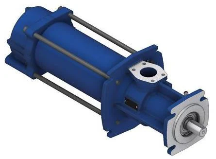
Symmetrical internal components equal exceptionally long service life. A single external radial bearing and a component mechanical seal are the only wear items outside the rotor set.
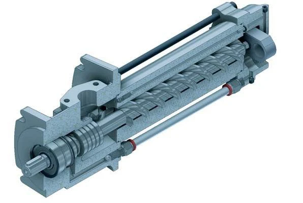
- CasingVariety of metals available: cast iron, 316 stainless steel, carbon steel, aluminum.
- Triple rotor screw setNitride-hardened steel; one driven power rotor and two idler rotors.
- Mechanical sealComponent mechanical seal as standard, plus other options.
- External ball bearingSingle radial bearing; rotor pressure loads are balanced hydraulically.
- DischargeFlanged discharge connection at the drive end of the casing.
- SuctionFlanged suction connection at the far end of the casing.
- Pressure knockdown bushingClose-clearance bushing behind the rotor set, significantly reduces the product pressure into the mechanical seal chamber.
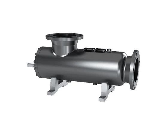
Performance and construction
Performance range
Performance range
| Flow rates | 1 – 1,428 GPM(44 – 48,900 BPD) |
|---|---|
| Pressures | up to 2,175 PSI |
| Viscosities | 1.2 – 5,000 cP |
| Working temperatures | to 302 °F |
| RPM range | 700 – 3,600+ |
| Horsepower | fractional to 500 HP |
| API compliance | API 676 models |
| Noise, average | 60 – 75 dB(A) @ 1,800 RPM |
Contact SPS for lower than 1.2 cP applications.
Materials of construction
| Casing | Cast iron, 316 S.S., carbon steel, aluminum |
|---|---|
| Screws / rotors | Nitride-hardened steel, plus other options |
| Seals | Component mechanical seals, plus other options |
| Bearing | Single radial bearing |
Applications
Model selection
Typical performance range
Seven frame sizes cover the TSP range. Select the smallest frame whose range brackets the duty flow, then confirm speed against viscosity.
| Pump model | Min flow — GPM | Min flow — BPD | Max flow — GPM | Max flow — BPD |
|---|---|---|---|---|
| SPS-TS-SM-CX | 1 | 44 | 16 | 548 |
| SPS-TS-SM-DX | 3 | 108 | 25 | 857 |
| SPS-TS-SM-EX | 7 | 240 | 72 | 2,468 |
| SPS-TS-SM-FX | 16 | 548 | 119 | 4,080 |
| SPS-TS-SM-GX | 21 | 720 | 166 | 5,692 |
| SPS-TS-SM-HX | 76 | 2,606 | 297 | 10,184 |
| SPS-TS-SM-IX | 117 | 4,011 | 467 | 16,013 |
GPM and BPD are based on 1.2 cP viscosity and 1,450 PSI discharge pressure. Higher viscosities increase flow rates and overall efficiency. Pumping efficiencies as high as 90+ %. Horsepower range from fractional to 500 HP.
SPS commitment
Rock solid pumping solutions you can trust
SPS Triple Screw Pumps are part of our ongoing products and services designed to increase your company's productivity and revenues. Our pumps and pump systems bring innovation, unique design, engineering and quality. At SPS, our goal is to significantly reduce your installation and overall operation and maintenance costs. Our TSP pumps are important to achieving this commitment.
Send us the duty point, fluid, viscosity and temperature and we will return a TSP frame selection.
Request a TSP selection